
Waterproof enclosure design begins with the possible water-entry paths around the housing. In most product housings, the main risk areas are the parting line between two housing halves, screw holes, cable entries, connector openings, button areas, display windows, and vent locations.
The IP code gives a useful language for this work. IEC explains that the first IP digit refers to protection against solid objects and dust, while the second digit refers to protection against water. In enclosure design, that rating is not achieved by one feature alone. A housing usually needs the right joint geometry, seal compression, screw layout, cable sealing, material choice, and pressure relief strategy to work as a system.
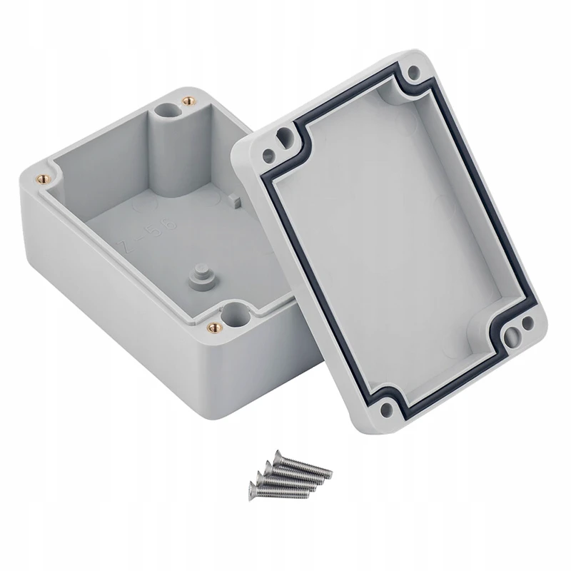
Start With the Water Path
A waterproof housing should be designed from the outside inward. Rain, spray, condensation, cleaning water, and brief immersion behave differently. A wall-mounted outdoor controller may need drainage and cable glands. A handheld instrument may need sealed buttons and a stable grip surface. A sensor box in a greenhouse may face humidity every day, even if it is never submerged.
The enclosure should guide water away from weak points before the seal carries the remaining load. Raised lips, tongue-and-groove joints, protected parting lines, recessed screw areas, and downward-facing cable exits can all reduce gasket stress. If the joint geometry is weak, adding more sealant usually makes maintenance harder without improving consistency.
Gasket Sealing
Silicone gaskets, O-rings, and flat sealing strips are often used when the enclosure must remain serviceable. The groove and compression design determine whether the seal is stable. The gasket needs a controlled seat, a smooth contact surface, enough compression to seal, and enough space to avoid being cut or squeezed out.
For many small plastic enclosures, the gasket groove is placed around the internal cavity, and the lid is pulled down by screws. Corners need special attention. If the screws are too far apart near a corner, the lid can lift slightly and leave a leak path. If the groove has burrs, flash, or a sharp edge, the seal may fail even when the drawing looks correct.
Hammond's gasketed enclosure series is a useful reference point here because its water-tight housings use thick walls, lid sealing, and environmental protection claims up to IP68/NEMA 6P on selected models. The important lesson is structural: the gasket, cover, wall stiffness, and screw positions work together.
Screw Areas
Screw locations need to be reviewed as part of the sealing boundary. A screw hole can become a direct water path if it passes from the wet side into the internal cavity. A safer layout keeps screw holes outside the gasketed area, or places the screw bosses inside a protected sealing boundary. If a screw must pass through a wet side, the design may need a washer, sealing boss, or local sealant.
This is where enclosure design becomes practical rather than decorative. The screw pattern is not only about assembly strength. It also controls lid flatness and seal pressure. A lid that looks flat in CAD may still bow between fasteners after molding, painting, or repeated opening.
Cable Entry and Connectors
Cable entries should be treated as part of the enclosure, not as a late opening added after the shell is finished. A cable gland clamps the cable, seals around it, and provides strain relief. Polycase describes cable glands as assemblies with a body and nut, with gasket and cable seal features either integrated or separate. Takachi also notes that cable glands are used to fix cables into enclosures and protect against water, oil, or dust.
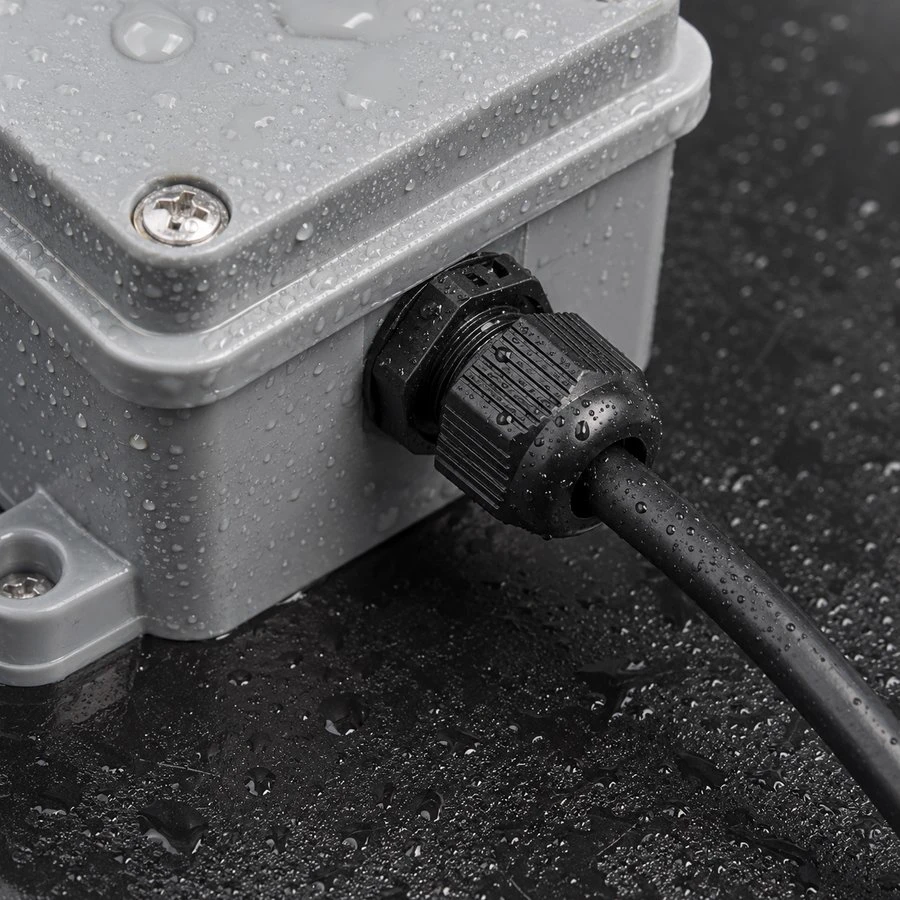
The enclosure wall must leave enough flat area for the gland nut, gasket, wrench access, and cable bend radius. If the cable exits upward on an outdoor box, water can run along the cable toward the opening. A downward or side-facing entry, paired with a drip loop during installation, is usually easier to control.
Connectors follow the same rule. A normal pin header or exposed socket cannot become waterproof just because the outer shell is sealed. If the connector is exposed to water, the connector itself needs a suitable sealing design.
Buttons and User Interfaces
Buttons are another common leak point. A separate plastic button passing through the shell creates a moving gap, so outdoor and wet-use products often use silicone keypads, molded rubber membranes, or sealed switch caps. Display windows need adhesive, gasket, or overmolded sealing around the perimeter. The sealing method should be chosen before the front panel layout is frozen.
The surface around buttons also matters. Deep recesses collect water and dirt. Raised features may protect the button from accidental impact but can make wiping harder. For products used in workshops, kitchens, gardens, entryways, or factory floors, cleaning should be considered during the enclosure layout stage.
Pressure Equalization
Sealing also changes the pressure behavior of the housing. Temperature changes, sunlight, altitude change, and device heat can create pressure differences between the inside and outside of the enclosure. GORE describes protective vents as parts that equalize pressure differentials and reduce stress on seals and connectors in sealed enclosures. This is why many outdoor and sealed electronics use breathable vents rather than relying only on tighter joints.
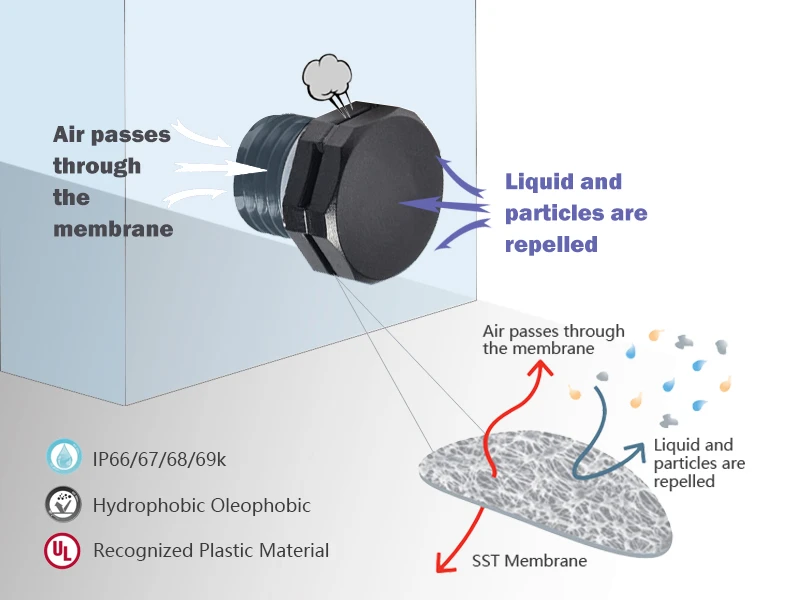
Vent placement should avoid standing water, splash concentration, labels, foam tapes, and internal parts that block airflow. The vent should be treated as part of the housing strategy, together with gasket quality, cable entry, assembly torque, and test conditions.
Material and Wall Thickness
Plastic choice affects sealing. ABS and PC are common for product housings, while PC is often selected when impact resistance or outdoor use is important. PP can be useful for chemical resistance and flexibility, but welding and dimensional control may require more care. Brittle materials, thin walls, or weak bosses can make gasket compression unreliable.
Wall thickness should support the sealing load. If the lid bends under screw pressure, the gasket compression becomes uneven. If a boss is too thin, it may crack during assembly. If the parting line is too flexible, a product may pass a quick spray test but fail after thermal cycling or repeated service.
Structure Checklist
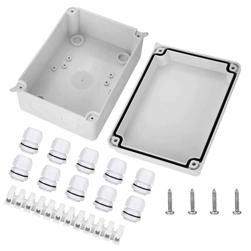
Before tooling, check the housing as a complete waterproof system:
- Parting line position and water flow direction
- Gasket groove depth, width, corner radius, and compression
- Screw spacing near corners and long edges
- Screw holes inside or outside the sealing boundary
- Cable gland flat area, thread length, and wrench access
- Connector sealing method
- Button and display window sealing
- Vent location and airflow path
- Material stiffness, wall thickness, boss strength, and molding tolerance
- Assembly torque and service requirements