Large plastic enclosures are rarely difficult because of one isolated feature. The challenge comes from scale. A gap that looks minor on a handheld device can become conspicuous across a long cover. A wall that appears stiff in CAD may flex after molding. A locating feature that works on a small box may not control two large shells well enough during assembly.
This is common in medical equipment, industrial instruments, test systems, kiosks, laboratory devices, and other products built in modest volumes. The enclosure has to carry the product's appearance, but it must also locate displays, doors, brackets, wiring, PCBs, and service panels. Those requirements should be settled before choosing a manufacturing process.
What Counts as a Large Plastic Enclosure?
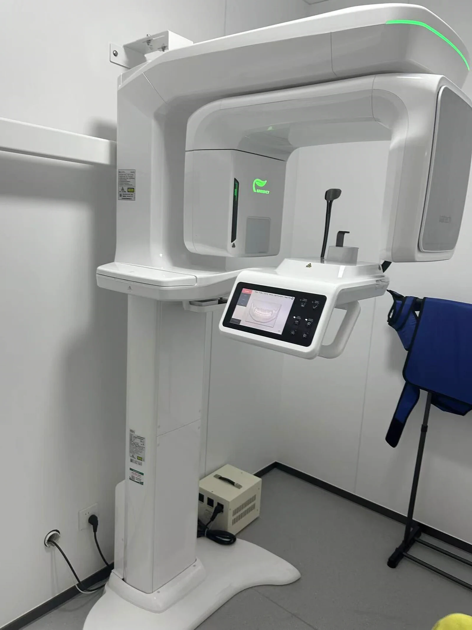
There is no universal dimension at which an enclosure officially becomes large. A 350 mm cover with shallow walls may be easier to control than a 250 mm part with deep ribs, a glossy surface, and several mating interfaces. Size matters, but so do wall depth, material shrinkage, geometry, finish, and how many parts must line up.
For design review, it is more useful to ask four questions:
- Is the shell large enough to flex under its own weight or under screw load?
- Will shrinkage or forming variation be visible along a long joint?
- Do several panels need to meet at the same corner or reference plane?
- Does the enclosure need molded internal features, or can brackets and inserts be added later?
If any answer is yes, the project should be treated as a large-enclosure problem even when the overall dimensions are not exceptional.
Control the Joint Before Refining the Surface
The joint between two enclosure halves is where dimensional variation becomes visible. Long, straight split lines are especially unforgiving. If one panel bows or shifts, the gap can widen at the center, close at a corner, or create a step between adjacent surfaces.
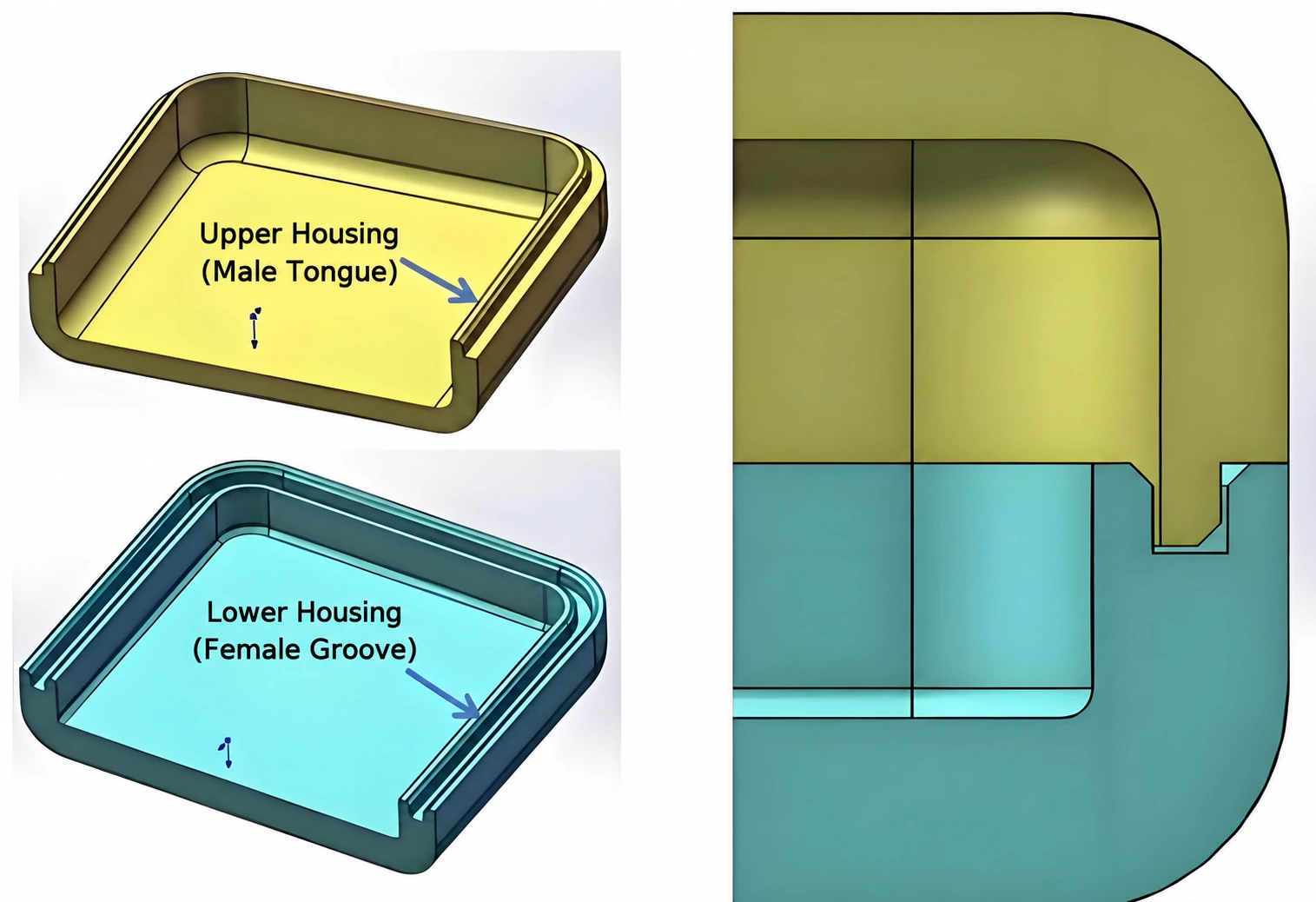
A tongue-and-groove or double-lip joint gives the two shells a physical locating path. One side enters the matching channel before the fasteners are tightened. This helps control lateral movement and can hide part of the direct sightline through the joint. The joint still needs clearance. If it is designed with almost no allowance, normal process variation may make the parts difficult to assemble.
Gap targets should come from process capability and the visible length of the seam, not from a cosmetic number copied from a smaller product. A slightly wider but even gap often looks better than a narrow gap that changes width. The CAD model should also identify which surface controls the final step height and which features are allowed to absorb variation.
Avoid Using Fasteners as Locating Features
Screws should clamp parts after they are positioned. They should not be expected to pull two flexible shells into alignment. On a large enclosure, that approach can leave one corner correct while another corner remains offset.
Use deliberate locating points instead. Depending on the process, these may include:
- tongue-and-groove joints along the perimeter
- pins and slots that define position without over-constraining the part
- broad ledges that support a removable panel
- metal brackets that connect the cosmetic shell to a rigid internal frame
- bonded blocks or inserts for processes that cannot form complex internal features
Long parts also need a sensible locating hierarchy. One fixed datum, one directional datum, and one floating area are often more reliable than several tight pins competing with one another.
Stiffness, Ribs, and Internal Mounting
Increasing wall thickness is not the only way to stiffen a large housing. It can add weight, extend cooling time, raise material use, and make molded sections more prone to sink or warp. Protolabs notes that injection-molded wall thickness should be kept reasonably uniform because thick areas cool differently and can distort the part. Ribs, returns, curved surfaces, and an internal frame are often more effective than simply making every wall thicker.
Internal construction depends heavily on the chosen process. Injection molding can form ribs, bosses, clips, and cable guides as part of the shell. Thermoformed parts generally have simpler back surfaces, so secondary blocks, brackets, or bonded inserts may be needed. CNC machining offers accurate pockets and holes, but deep internal details and undercuts are limited by cutter access.
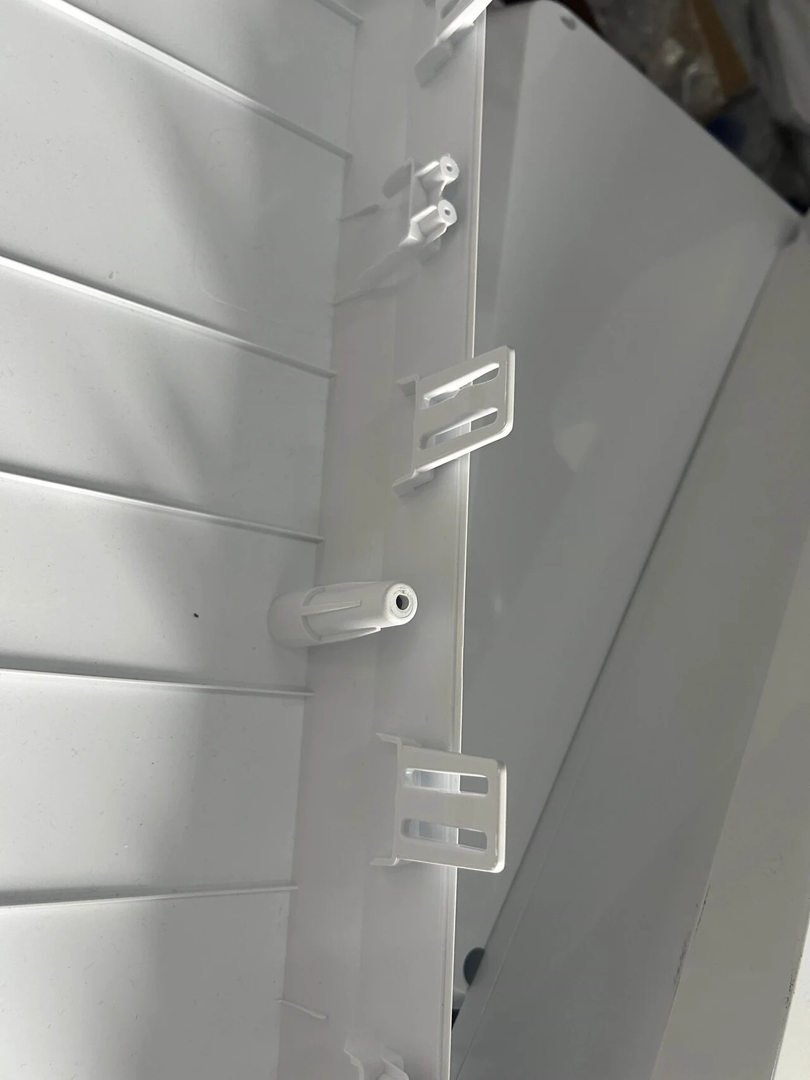
Bosses should not be placed without considering the outer surface. A heavy boss behind a cosmetic wall may leave a sink mark. On a large panel, bosses also need enough support to avoid bending the wall when screws are tightened. Connecting a boss to nearby ribs or a structural frame is usually more stable than leaving it as a tall isolated post.
Surface Finish and Color Do Not Correct Geometry
White and light neutral colors are common on medical and laboratory equipment because they fit the environment and make cleaning easier to assess. That does not mean white automatically hides every problem. Gloss level, lighting direction, texture, and panel curvature all affect whether waviness, scratches, sink, or mismatched gaps remain visible.
Finish should be chosen with the process. A machined plastic prototype shows tool paths unless it is sanded, polished, painted, or textured. Vacuum-cast polyurethane can reproduce the master pattern closely, including flaws left on that pattern. Thermoforming stretches a sheet over a tool, so texture and gloss can change in high-draw areas. Injection molding gives more repeatable production surfaces, but draft, gate location, weld lines, ejector marks, and local shrinkage still need to be planned.
Choosing a Manufacturing Process
Production quantity matters, but it is not enough to choose the process by itself. A better comparison includes enclosure size, required material, dimensional tolerance, finish, internal detail, expected design changes, tooling budget, and total lifetime volume.
1. 3D Printing
3D printing is useful while the architecture is still changing. It can confirm overall proportions, access panels, split lines, component clearance, and how the enclosure breaks into manufacturable parts. Large shells may need to be printed in sections and bonded, which can affect strength and surface finish.
Printed parts are not automatically equivalent to molded production parts. Material behavior, layer direction, long-term dimensional stability, and finish vary by printing process. Use the prototype to answer defined questions rather than treating it as proof that every production detail is resolved.
2. CNC Machining
CNC machining is a strong option for a small number of functional housings when dimensional control and production-grade plastic matter more than tooling cost. Protolabs notes that machined prototypes can use plastics close to those intended for later molding, and that machining avoids dedicated mold investment.
Cutter access sets the geometry. Deep narrow pockets, internal undercuts, and molded-style clips can be difficult or expensive. A practical enclosure may be divided into machined panels or use separately made tabs, brackets, or inserts. If injection molding is planned later, the machined prototype should not accidentally lock in features that cannot be molded.
3. Vacuum Casting
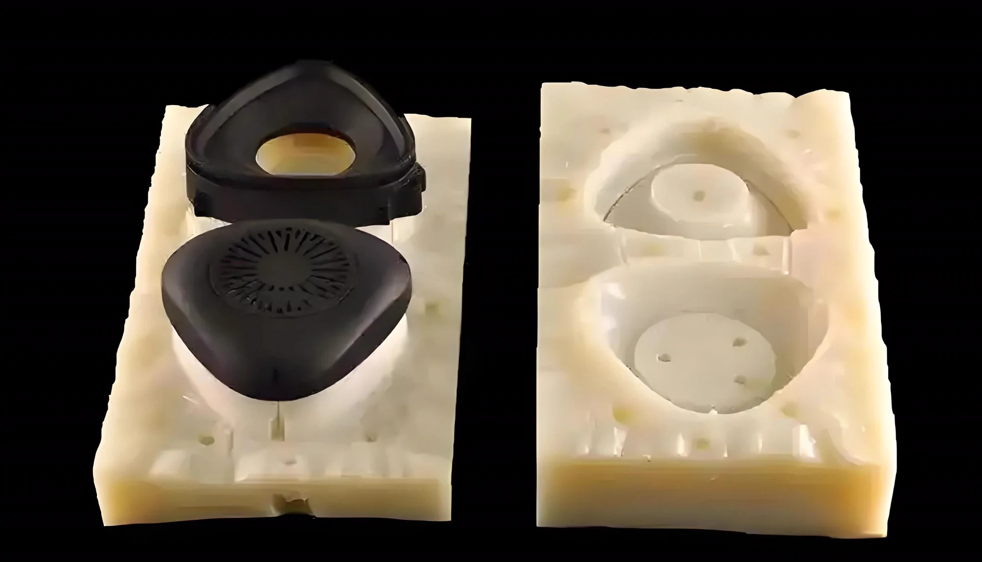
Vacuum casting, also called urethane casting, reproduces a master pattern in a silicone mold. It works well when a project needs a limited batch with a molded appearance before committing to production tooling. The master controls the final geometry and finish, so defects on the master are reproduced too.
Silicone molds have a finite working life, and the number of usable parts varies with part geometry, resin, mold design, and quality requirements. It is safer to quote each project than to promise a fixed number of parts from every mold.
4. Reaction Injection Molding
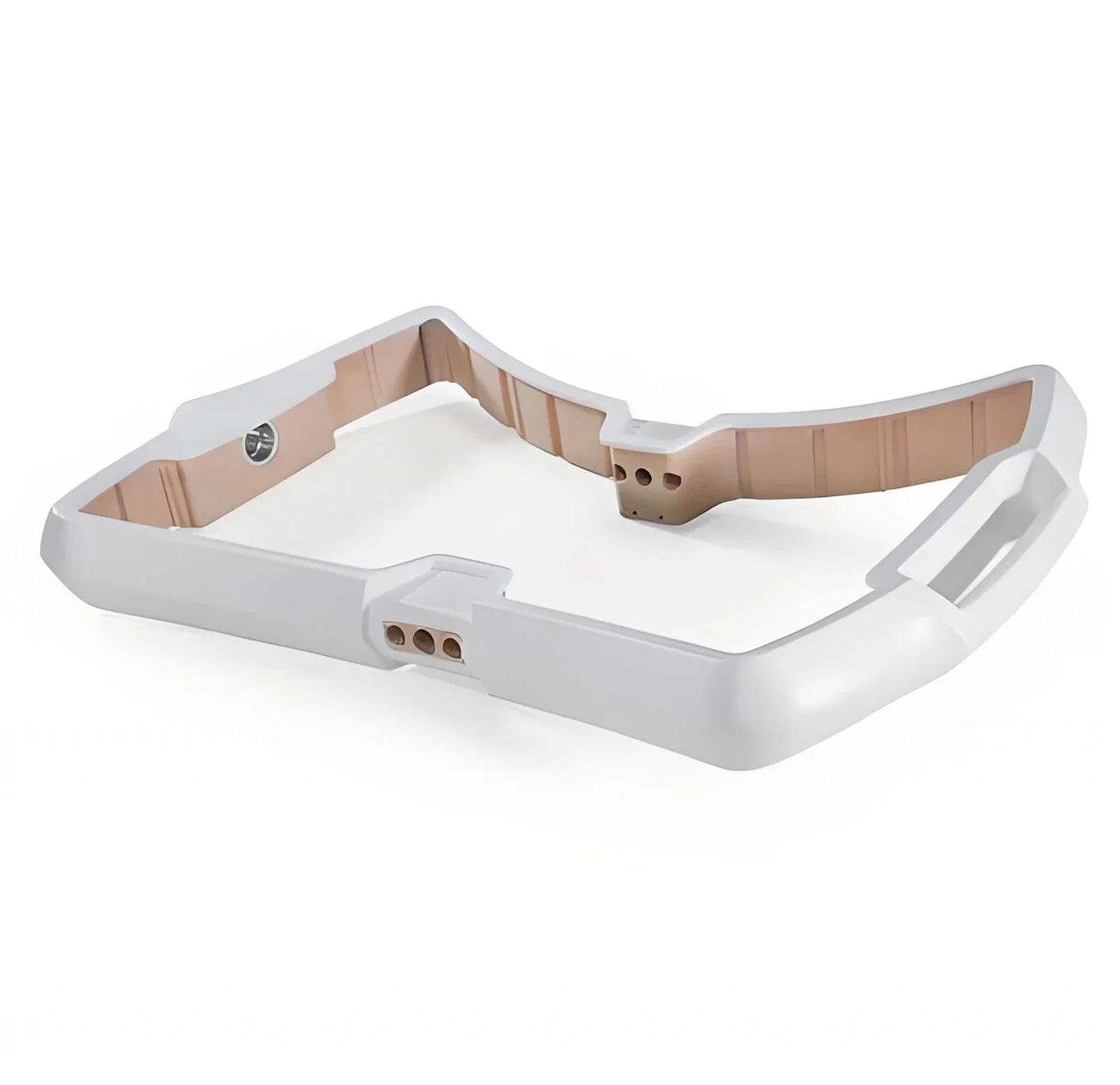
Reaction injection molding, or RIM, mixes liquid polyurethane components and sends the reacting material into a closed mold. Covestro describes the liquid as flowing into the mold at approximately atmospheric pressure after high-pressure mixing. The low-viscosity mixture can fill large tools, and polyurethane systems can be formulated from flexible to rigid.
RIM is often considered for large, lower-volume panels that would be expensive to produce with conventional thermoplastic injection tooling. It still requires project-specific engineering. Material properties, wall section, inserts, paint system, cycle time, and tool construction all affect the result.
5. Heavy-Gauge Thermoforming
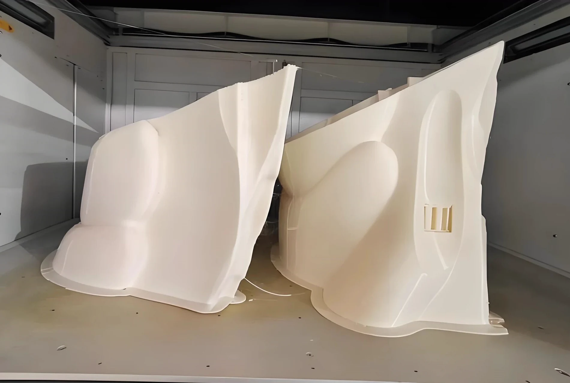
Thermoforming heats a plastic sheet and forms it over or into a tool. Vacuum or pressure helps the sheet follow the tool surface. Tooling is generally simpler than a full injection mold, which makes the process attractive for large covers, equipment skins, trays, and panels.
The trade-off is the back side of the part. The sheet stretches during forming, so wall thickness is not uniform throughout a deep draw. Fine ribs, screw bosses, and complex clips are not formed as they would be in injection molding. Draft, radii, draw ratio, trimming, and secondary mounting hardware must be considered from the start.
6. Injection Molding
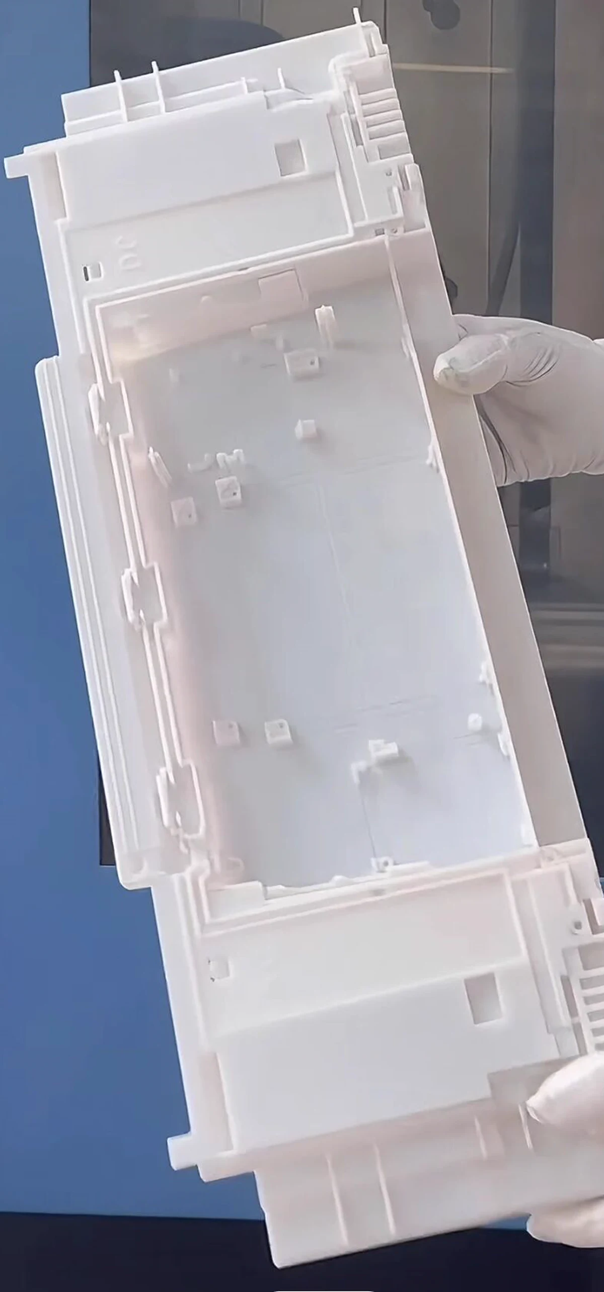
Injection molding becomes attractive when the enclosure design is stable and expected volume can support dedicated tooling. It can integrate bosses, ribs, snap features, vents, and repeated cosmetic details into the part. For a large enclosure, however, the mold, molding machine, handling equipment, cooling strategy, and risk of dimensional variation all become more demanding.
Draft and radii matter. Protolabs explains that draft reduces drag during ejection and that rounded corners improve material flow and part strength. The exact values depend on wall depth, material, texture, shrinkage, and the mold builder's process. Large housings also need early review of gate location, weld lines, cooling, ejector placement, flatness, and the way the two halves will be measured after molding.
A Practical Selection Table
| Process | Best used when | Main limitation to review |
|---|---|---|
| 3D printing | The enclosure is still changing or a physical layout model is needed | Material behavior, section bonding, and finish may differ from production |
| CNC machining | A few accurate functional parts are needed without tooling | Cutter access, material waste, and cost on large complex shells |
| Vacuum casting | A limited batch needs a molded appearance | Mold life and repeatability depend on the master and part geometry |
| RIM | Large polyurethane panels are needed at lower or moderate volume | Material system, paint, tool design, and process capability are project-specific |
| Thermoforming | Large covers need relatively simple geometry and economical tooling | Variable wall thickness and limited molded-in internal detail |
| Injection molding | The design is stable and repeat production justifies tooling | High initial tooling commitment and tighter DFM requirements |
These are starting points, not fixed volume rules. A large simple panel and a smaller enclosure with many undercuts can reach different cost breakpoints. Quotations should compare the complete program, including tooling changes, secondary operations, finishing, assembly fixtures, inspection, and expected repeat orders.
Design Review Checklist
Before releasing a large enclosure for prototype or tooling, review:
- product dimensions, wall depth, and unsupported panel spans
- the locating strategy between every shell and panel
- nominal gap and step targets at visible joints
- flatness and deformation limits tied to actual assembly needs
- screw pattern, clamp load, and access for service
- ribs, bosses, brackets, inserts, and internal frame connections
- clearance for PCBs, displays, wiring, fans, filters, and connectors
- draft, radii, undercuts, and tool access for the selected process
- surface texture, gloss, color, paint, and acceptable witness marks
- inspection datums and a repeatable method for checking the assembled housing
- prototype quantity, launch quantity, and expected lifetime demand
Final Decision: Start With the Product, Not the Process
A large enclosure should not be forced into a manufacturing method simply because that method worked on a previous project. First settle how the product is assembled, which surfaces the user sees, where stiffness comes from, how internal hardware is mounted, and what variation the visible joints can tolerate.
TY Enclosure supports custom plastic and metal housing projects from structural review through prototype and production planning. For a large plastic enclosure, we can compare the CAD structure, material, surface requirement, internal hardware, production quantity, and future tooling route before the design is committed to one process.