An outdoor electronic device can have a properly designed waterproof enclosure and still experience moisture-related problems inside the housing.
For an Original Equipment Manufacturer (OEM), this can be difficult to understand. The enclosure may use gaskets, sealed cable entries, and materials selected for outdoor exposure. Its design may also target an IP67 ingress protection rating.
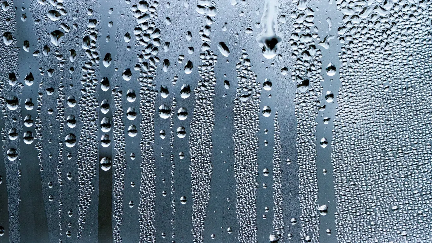
Yet, after repeated temperature changes, moisture can accumulate inside the product. Under certain conditions, water may condense on internal surfaces or PCB assemblies, increasing the risk of electrical leakage and corrosion.
The problem becomes particularly frustrating when a device has passed initial inspection or a water-ingress test but later develops intermittent failures during operation.
Scientific research shows why this can happen.
In 2016, researchers at the Technical University of Denmark investigated humidity accumulation in electronic enclosures exposed to temperature cycling. Their experiments demonstrated that enclosure openings, internal thermal mass, and contamination on PCB surfaces could substantially affect moisture accumulation and electrical leakage current.
In the most severe experimental conditions, the measured leakage current on contaminated PCB test patterns reached approximately 10 mA, compared with no more than approximately 1 μA on clean patterns.
These results were reported in Humidity Build-Up in a Typical Electronic Enclosure Exposed to Cycling Conditions and Effect on Corrosion Reliability, published in IEEE Transactions on Components, Packaging and Manufacturing Technology.
Importantly, the researchers used commercially available IP66/IP67-rated polycarbonate enclosures but deliberately introduced small openings to simulate leakage paths. The results should therefore not be read as proof that an intact, properly tested IP67 enclosure would behave identically.
Instead, the study demonstrates a broader engineering problem. Protecting electronics against liquid water entering from outside is not the same as controlling moisture, condensation, and corrosion risk inside the enclosure.
That distinction matters when developing housings for industrial sensors, outdoor controllers, communication equipment, monitoring devices, and other electronic products exposed to changing environmental conditions.
What Does IP67 Actually Protect Against?
The IP Code is defined by IEC 60529, Degrees of Protection Provided by Enclosures.
An IP67 designation combines two protection classifications.
The first digit, 6, indicates a dust-tight enclosure.
The second digit, 7, indicates protection against the harmful effects of temporary immersion in water under specified test conditions.
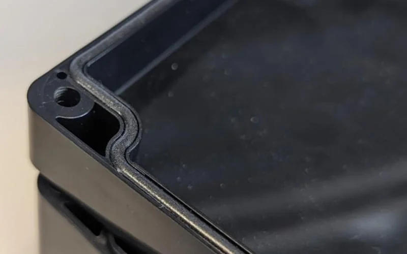
These classifications are useful for evaluating the enclosure's resistance to external contaminants.
IP67 does not establish, however, that the internal air will remain dry under every operating condition.
Nor does the rating automatically demonstrate resistance to repeated temperature cycling, long-term water vapor diffusion, or condensation on internal electronic components.
The distinction matters because liquid-water ingress and internal condensation involve different physical mechanisms.
A water-ingress test evaluates the enclosure under specified external exposure conditions.
Condensation occurs when a surface becomes sufficiently cold relative to the moisture content of the surrounding air for water vapor to form a liquid water layer.
An enclosure can contain water vapor even when no liquid water is visibly entering through its joints.
Moisture may have been present during assembly, introduced during maintenance, transmitted through some materials over time, or transported through imperfect seals and other interfaces.
The potential for condensation therefore depends on internal moisture content and temperature conditions, not simply on whether an enclosure resists temporary immersion.
For an OEM, an IP67 requirement and a humidity-reliability requirement should be treated as related but separate design considerations.
Why Temperature Changes Can Create Water Inside an Enclosure
Condensation is closely connected to the relationship between air temperature, water vapor, and dew point.
Warm air can contain more water vapor at saturation than cold air.
When moisture-containing air cools, its relative humidity increases even if no additional water vapor has entered.
If an internal surface falls below the dew point of the air in contact with it, water vapor can condense on that surface.
This can occur during outdoor temperature changes or during transitions between powered and unpowered operating conditions.
Consider an electronic controller installed outdoors.
During operation, the PCB, power components, and other internal parts may generate heat.
When the equipment is switched off, the internal temperature begins to change.
The housing may also respond to changing solar exposure, rain, ambient temperature, or other environmental conditions.
Different components do not necessarily heat up or cool down at the same rate.
A large metal bracket, heat sink, or other internal structure may store thermal energy and create local temperature differences.
These temperature differences can affect where condensation is most likely to occur.
The Danish researchers examined precisely this relationship between external temperature cycling, internal heating, and thermal mass.
Their work demonstrated that the internal humidity response can differ significantly from the ambient humidity profile.
Consequently, monitoring only the outside temperature, or selecting an enclosure with an appropriate water-ingress rating, may not provide enough information to assess internal condensation risk.
Experimental Evidence: A 10–50°C Temperature Cycle Increased Internal Humidity
The 2016 IEEE study provides unusually detailed experimental evidence.
The researchers used polycarbonate enclosures measuring approximately 280 × 190 × 130 mm.
The original enclosures had an IP66/IP67 rating. To investigate moisture exchange through possible leakage paths, the researchers drilled controlled openings with diameters of either 1 mm or 3 mm.
The test environment was established in a climatic chamber.
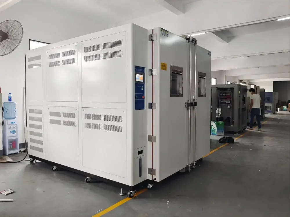
The principal experimental conditions included:
| Experimental parameter | Value |
|---|---|
| Enclosure material | Polycarbonate |
| Enclosure dimensions | 280 × 190 × 130 mm |
| Simulated leakage openings | 1 mm or 3 mm diameter |
| External temperature cycle | 10°C to 50°C |
| Chamber relative humidity | 98% |
| Internal heater operating period | 45 minutes ON, 2 hours 15 minutes OFF |
| Evaluated internal thermal mass | 40 cm³ or 80 cm³ |
| PCB leakage-current test bias | 5 V DC |
The chamber temperature changed repeatedly between the specified limits, while internal heating was deliberately offset from the external temperature cycle.
This created temperature differences between the enclosure environment and the internal components.
During the experiments, the researchers monitored temperature, relative humidity, and absolute humidity.
They found that moisture content inside the enclosure increased during repeated cycles.
For the empty enclosures, the absolute humidity measured near the end of the experiment at 50°C reached approximately:
- 36 g/m³ with the 1 mm opening.
- 51 g/m³ with the 3 mm opening.
Under these particular conditions, the larger opening allowed more rapid moisture exchange and greater water-vapor accumulation.
At the lower temperature of 10°C, the internal air approached saturation, creating conditions favorable to condensation.
This matters because the openings were not simply acting as pathways for liquid water. They also permitted moisture-containing air to enter and leave the enclosure as temperatures changed.
The study describes this repeated exchange and moisture accumulation as a humidity-pumping effect.
The findings do not mean that a 3 mm opening will always produce more condensation than a 1 mm opening in every enclosure.
The result depends on the experimental temperature profile, internal volume, thermal conditions, and surrounding humidity.
The practical conclusion is that small openings and imperfect sealing interfaces can significantly influence internal moisture behavior during repeated environmental changes.
Internal Heat Sinks Can Change Condensation Risk
The Danish researchers also investigated how internal thermal mass affected moisture accumulation.
They introduced aluminum thermal masses of 40 cm³ and 80 cm³ to represent heat-conducting structures associated with electronic equipment.
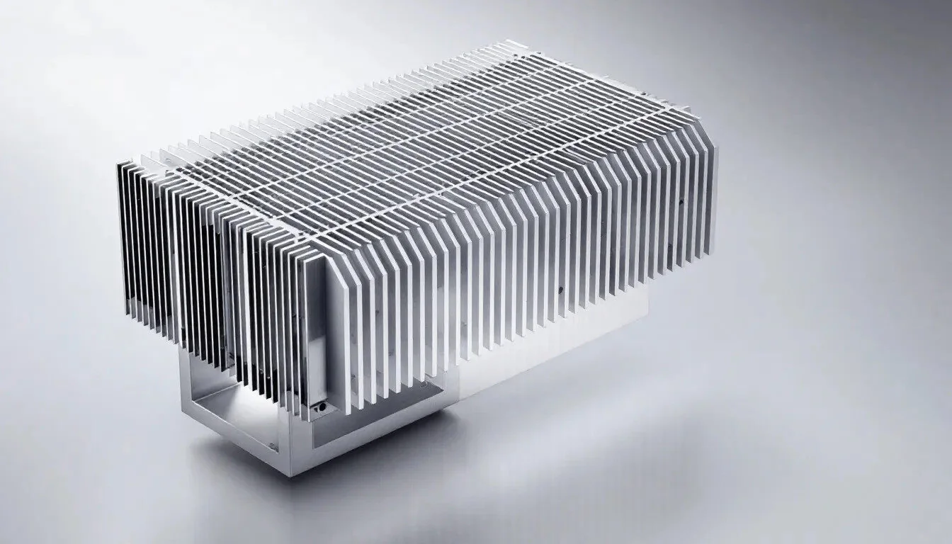
A PCB test pattern was positioned in relation to these thermal masses.
The results showed that the presence of thermal mass changed the temperature response and increased humidity accumulation under the tested conditions.
For example, with a 1 mm opening, the absolute humidity ranges measured during the final cycle were approximately:
| Internal configuration | Reported absolute humidity range |
|---|---|
| No thermal mass | 9–34 g/m³ |
| 40 cm³ thermal mass | 12–51 g/m³ |
| 80 cm³ thermal mass | 12–58 g/m³ |
These ranges reflect different temperature points during the experimental cycle; they are not three measurements taken simultaneously at an identical temperature.
The results show how thermal structures can affect the internal moisture environment.
One consequence is that heat sinks are not relevant only to thermal management.
Their mass, material, position, and temperature response can also affect moisture behavior near the PCB.
This is especially relevant to electronic equipment containing power modules, metal mounting plates, or substantial heat sinks.
It would be incorrect to conclude that increasing the size of a heat sink always increases condensation.
The experimental outcome depends on the full thermal and moisture environment.
These findings do show why enclosure design should consider thermal and humidity behavior together rather than treating them as unrelated engineering concerns.
Experimental Evidence: PCB Contamination Increased Leakage Current by Orders of Magnitude
The same 2016 research also investigated the electrical consequences of moisture accumulation.
The researchers placed surface insulation resistance test patterns inside the enclosures.
These PCB test structures contained closely spaced conductive electrodes designed to reveal changes in surface electrical leakage.
Three contamination conditions were evaluated:
- No added sodium chloride.
- 1.56 μg/cm² sodium chloride.
- 15.6 μg/cm² sodium chloride.
The researchers applied a constant 5 V DC bias and monitored leakage current during the temperature and humidity cycles.
The recorded peak values differed substantially.
| PCB test condition | Reported peak leakage current |
|---|---|
| Clean test pattern | Up to approximately 1 μA |
| 1.56 μg/cm² NaCl contamination | Approximately 1 mA |
| 15.6 μg/cm² NaCl contamination | Approximately 10 mA |
These are peak results from the study's tested configurations, not typical leakage-current values for commercial electronic products.
The measurement was performed using a specific interdigitated test pattern under deliberately severe temperature, humidity, and contamination conditions.
The difference is still substantial: the higher contamination levels produced leakage currents several orders of magnitude greater than those measured on clean test patterns.
The researchers also examined the PCB surfaces after testing using optical microscopy and scanning electron microscopy.
Corrosion products were observed on contaminated patterns, with more severe degradation under higher contamination and thermal-mass conditions.
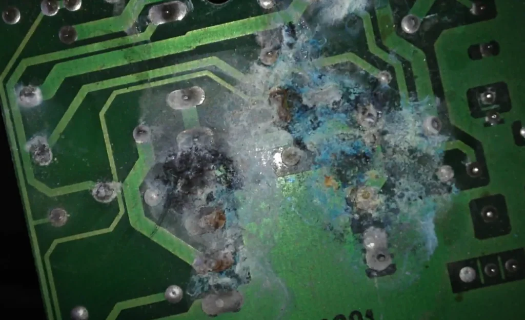
The study did not establish electrochemical migration dendrites as the cause of these particular leakage-current changes.
Instead, it identified moisture-assisted ionic conduction and corrosion-related surface changes.
For OEMs, the practical implication is that an enclosure's humidity behavior cannot be separated entirely from the cleanliness and protection of the electronics inside it.
Even when a relatively small amount of moisture is present, contamination can influence whether an electrically conductive surface layer forms.
A successful enclosure design therefore needs to be compatible with the electronic assembly's actual reliability requirements.
A Short Period Near the Dew Point Can Also Matter
Condensation risk is not limited to prolonged exposure to visibly wet conditions.
A 2022 study published in Microelectronics Reliability, titled Transient Risk of Water Layer Formation on PCBAs in Different Climates: Climate Data Analysis and Experimental Study, investigated short periods during which ambient temperature approaches the dew point.
The researchers analyzed climatic conditions across different geographical regions.
They identified events where the difference between air temperature and dew point was 0.4°C or less.
This threshold was used to identify conditions close to saturation.
Their analysis found that such events occurred across nearly all of the examined locations, although their frequency, duration, and temperature varied.
The researchers then performed laboratory experiments to examine how these transient conditions affected PCB surface leakage.
The results showed that relatively short periods near condensation conditions could produce substantial leakage-current responses.
The study also found that the presence of an enclosure, cleaner PCB surfaces, and greater spacing between conductive features reduced leakage current under the examined conditions.
These findings matter because a product does not need to remain in a continuously humid environment to experience a moisture-related electrical problem.
Temporary environmental transitions may be sufficient to create unfavorable surface conditions.
This helps explain why some field failures can be intermittent.
An electronic device may behave differently after warming up, cooling down, or experiencing a change in ambient humidity.
Such behavior does not automatically identify condensation as the cause of a particular failure, but it shows why temperature and humidity histories can be important during diagnosis.
What a 2025 Thermal Study Reveals About Cold Enclosure Walls
More recent research has also examined how enclosure wall temperatures influence internal humidity distribution.
A study published in Applied Thermal Engineering in November 2025, Heat and Moisture Transfer Analysis in Electronic Equipment Cabin with Multiple Heat Sources, investigated the coupled effects of temperature, moisture, heat-source distribution, and airflow in electronic equipment compartments.
Unlike the 2016 IEEE experiment, this study used a finite-element numerical model rather than reporting the same type of enclosure-chamber measurements.
The researchers found that reducing the modeled enclosure wall temperature from 298.15 K to 283.15 K, equivalent to approximately 25°C to 10°C, produced a 69.6% increase in maximum relative humidity under the specified simulation conditions.
This is a relative percentage change in the model's reported maximum relative humidity, not a universal increase of 69.6 percentage points.
The study also found that changing the distribution of internal heat sources could substantially affect peak temperature while having a smaller effect on maximum relative humidity under the modeled conditions.
These results support a useful engineering principle.
The temperature of the enclosure wall can influence where moisture accumulates and whether local conditions approach condensation.
For example, a cold enclosure surface may create a different humidity environment from the air near an operating electronic component.
The design therefore needs to consider local temperature differences rather than assuming that one internal temperature measurement represents every surface.
The model's numerical results should not be applied directly to a small sealed IP67 enclosure without accounting for differences in geometry, airflow, moisture transport, and operating conditions, though.
The value of this research is in demonstrating the importance of coupled thermal and moisture analysis, not in providing a universal condensation prediction for every housing.
Are Plastic Enclosures More Vulnerable Than Metal Enclosures?
The choice between plastic and metal can influence moisture and temperature behavior.
Neither material automatically eliminates condensation risk, though.
Plastic enclosure materials differ in their water-vapor permeability, thermal conductivity, mechanical properties, and long-term environmental behavior.
Depending on the material and wall construction, moisture may diffuse through polymer walls over time.
Metal walls generally provide a much stronger barrier to water-vapor diffusion through the bulk material.
A metal enclosure can still exchange moisture through gaskets, cable entries, connector interfaces, or other non-hermetic joints.
Its internal temperature response can also differ from that of a plastic enclosure.
A 2022 experimental paper published in Mechanika, Experimental Investigation of Thermal and Humidity Dynamics in the Enclosures Made of Non-Permeable Walls, compared thermal and humidity behavior in aluminum and glass enclosures subjected to climatic cycling.
The researchers found different temperature distributions and responses associated with the enclosure materials and boundary conditions.
This was a comparison between aluminum and glass, not a controlled comparison of aluminum and a conventional plastic enclosure.
The results therefore should not be used to claim that all metal enclosures are more or less resistant to condensation than plastic ones.
For a real OEM project, the important variables include the housing material, wall thickness, internal volume, sealing interfaces, thermal design, and external environmental conditions.
Material selection is part of the solution, but it cannot replace evaluation of the completed enclosure system.
Can a Protective Vent Prevent Condensation?
Pressure-equalization vents are used in various outdoor electronic enclosures to reduce pressure differences caused by temperature and environmental changes.
A typical protective membrane vent allows air and water vapor to pass while resisting the passage of liquid water and selected contaminants under its specified operating conditions.
This can reduce pressure stress on seals and other enclosure interfaces.
A vent is not a dehumidifier, though.
W. L. Gore & Associates' technical FAQ on protective vents explains that moisture vapor can pass through breathable membranes in both directions.
According to Gore, this bidirectional exchange may help reduce moisture that would otherwise remain trapped within an enclosure.
But the same property means that a vent cannot guarantee a continuously dry internal environment when the outside air is humid.
Its effectiveness depends on the selected vent, airflow characteristics, installation position, environmental conditions, and enclosure design.
The distinction matters because a pressure-equalization vent and an intentionally uncontrolled leakage hole are not equivalent.
A protective vent is designed to meet defined requirements for airflow and resistance to liquid-water ingress.
A simple drilled hole provides no comparable protection by itself.
The 2016 IEEE study demonstrated what can occur when moisture exchange takes place through uncontrolled openings under severe cycling conditions.
It did not establish that an appropriately selected protective membrane vent would produce the same results.
For OEMs, protective vents should therefore be evaluated as engineered components with defined performance characteristics.
The finished enclosure still needs to satisfy the required ingress protection and humidity-reliability criteria.
Why Desiccant Packs Are Not Always a Permanent Solution
Another approach is to place moisture-absorbing material inside the enclosure.
Desiccants can reduce internal humidity by absorbing water vapor.
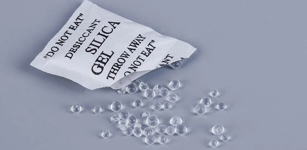
Their moisture capacity is finite, though.
If the absorbed moisture is not removed or the material is not regenerated, the desiccant eventually loses its ability to continue lowering humidity effectively.
A 2021 paper in IEEE Transactions on Components, Packaging and Manufacturing Technology, Humidity Control in Electronic Devices: Water Sorption Properties of Desiccants and Related Humidity Build-Up in Enclosures, investigated the performance of different desiccants under cyclic conditions.
The researchers examined both moisture absorption and regeneration behavior.
They found that desiccant systems could maintain lower enclosure humidity over the tested cyclic exposure when suitable regeneration was achieved using heat generated during device operation.
This does not mean that every electronic device can regenerate a desiccant simply by becoming warm.
The regeneration behavior depends on the desiccant, temperature, moisture conditions, and available heating cycle.
For products that spend long periods unpowered or operate in persistently humid environments, the suitability of a desiccant system requires particular consideration.
An OEM should therefore evaluate whether moisture absorption is intended as a temporary buffer, a serviceable component, or part of a specifically designed regenerative humidity-control system.
Adding a desiccant pack without assessing its service life should not be treated as a complete long-term condensation-control strategy.
What Should OEMs Test Before Approving an Outdoor Electronic Enclosure?
A suitable validation plan should reflect the product's actual operating environment.
IP testing remains important when the device requires defined protection against dust and external water exposure.
Internal humidity reliability may require additional tests, though.
The international standard IEC 60068-2-30:2025, Environmental Testing — Test Db: Damp Heat, Cyclic, specifies a procedure involving alternating high-humidity and temperature conditions using a 12-hour plus 12-hour cycle.
The standard is intended to evaluate the suitability of components, equipment, or other articles under cyclic damp-heat conditions that generally produce condensation on specimen surfaces.
It does not automatically provide a universal pass/fail threshold for every electronic product's internal leakage current or lifetime reliability.
Those acceptance requirements need to be defined according to the product and its application.
For an outdoor controller or monitoring device, a project-specific validation program may consider the expected temperature range, humidity conditions, operating duty cycle, enclosure orientation, and internal heat generation.
Measurements may include internal relative humidity, critical surface temperatures, visible condensation, electrical insulation or leakage behavior, and functional performance during and after exposure.
Where practical, the test configuration should represent the final product.
That includes the intended PCB, fasteners, gasket, cable glands, connectors, windows, venting components, and relevant internal thermal structures.
A housing tested without its final cable entries or other required modifications may not represent the configuration delivered to the customer.
The OEM should also determine whether the product needs to operate during the environmental test or only demonstrate acceptable function afterward.
These are different verification requirements.
A design that survives temporary immersion has not necessarily demonstrated acceptable behavior during repeated damp-heat exposure.
Likewise, passing a damp-heat test does not replace the required IP ingress-protection assessment.
Condensation Control Should Begin Before the Enclosure Design Is Finalized
When a product is still under development, the enclosure's moisture behavior can be considered alongside its mechanical and thermal requirements.
The first step is to identify the actual environment in which the electronic product will operate.
An outdoor sensor that remains energized continuously may experience different internal temperature cycles from a battery-powered device that wakes periodically.
A roadside controller may experience different moisture and temperature conditions from equipment installed in a temperature-controlled building.
These differences influence the appropriate enclosure design and validation approach.
Potential solutions may involve improvements to sealing interfaces, suitable pressure equalization, management of internal moisture, changes in thermal layout, or additional protection for moisture-sensitive electronic assemblies.
No single measure addresses every moisture-related failure mechanism, though.
A protective vent may reduce pressure stress but does not guarantee dry air.
A desiccant may absorb moisture but requires sufficient capacity and an appropriate long-term strategy.
An improved gasket can reduce external ingress through a particular joint, but cannot remove moisture already trapped during assembly.
Thermal design changes may reduce unfavorable temperature differences, but they should be evaluated against the product's cooling and operating requirements.
For an OEM, the objective is to establish how these measures work together before committing to the final enclosure configuration.
A manufacturer can then review the mechanical feasibility of the proposed seals, vents, mounting arrangements, materials, and other structural features.
Electrical and environmental validation should confirm whether the completed product meets the specified reliability requirements.
IP67 Protection and Long-Term Moisture Reliability Are Different Engineering Requirements
An IP67-rated enclosure can provide valuable protection against dust and specified external water exposure.
The IP rating alone does not establish that the internal environment will remain free of condensation throughout the product's service life, though.
Scientific research has demonstrated that repeated temperature changes, moisture exchange, thermal mass, and PCB surface contamination can interact in ways that affect electronic reliability.
The 2016 IEEE experiments showed how controlled leakage openings and temperature cycling could increase internal humidity, while contaminated PCB test patterns experienced leakage currents reaching the milliampere range.
The 2022 Microelectronics Reliability study demonstrated that even relatively short periods near dew-point conditions can affect electrical leakage.
More recent numerical research has shown that enclosure wall temperature and internal heat distribution can influence local humidity and condensation risk.
Together, these findings point to a broader design requirement. A reliable outdoor electronics enclosure must be evaluated not only for external water ingress, but also for the internal moisture and temperature conditions that its electronic components may experience.
For OEMs, this means defining the operating environment, required enclosure protection, internal thermal behavior, and appropriate verification methods before the design is released for production.
Tongyong Industries supports custom plastic and metal enclosure development through structural design review, material selection, PCB and component integration, prototyping, manufacturing, and testing coordination.
Through its enclosure design and engineering services, OEM customers can submit CAD drawings, STEP files, PCB layouts, environmental requirements, and existing housing designs for an initial mechanical design and manufacturing review.
Considering sealing, moisture behavior, thermal requirements, and assembly interfaces together can help identify potential enclosure-design problems before tooling and production begin.